Tools Introduction Class
Tools Feature & Advantage Introduction Class
Tools Operation and Application Class
Tools Maintanence and Repair Class
Tools Quality Checking and Certified Class
Tools Torque Introduction
Marketing Service Area
Member post
Assembling The Tool Storage Cabinets
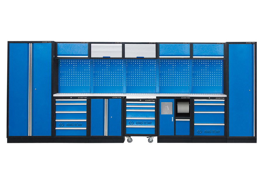
Popularity : 1083This time, we’re bringing up the exhaustive introduction of the system cabinets. The production code of The Series of 87D11 will be presented as examples in the following article.
Tall Cabinet
To begin with, assembling the Tall Cabinet will be necessary, and the production codes will be 87D11-02A or 87D11-18A.
| 1 door Tall Cabinet | 87D11-02A-KB 87D11-02A-KG |
| 2 doors Tall Cabinet | 87D11-18A-KB 87D11-18A-KG |
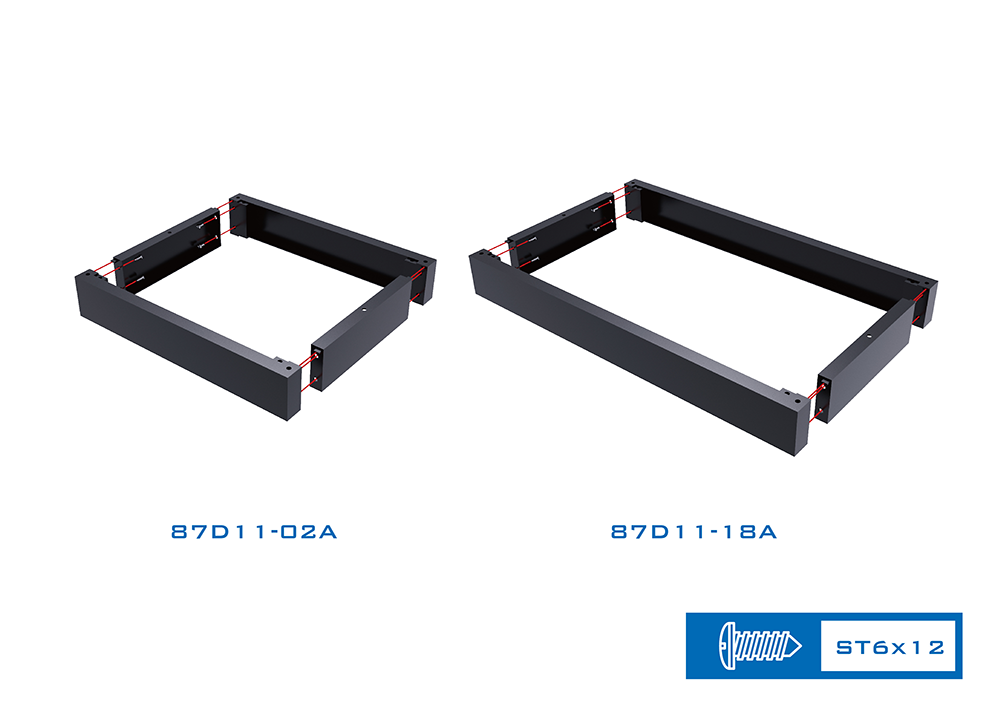
The base set of the bottom area is composed of four parts. It is noticeably that the components on the right and left are made with latches on top of them. Dock these two components with the front and back part, then tighten the screws.
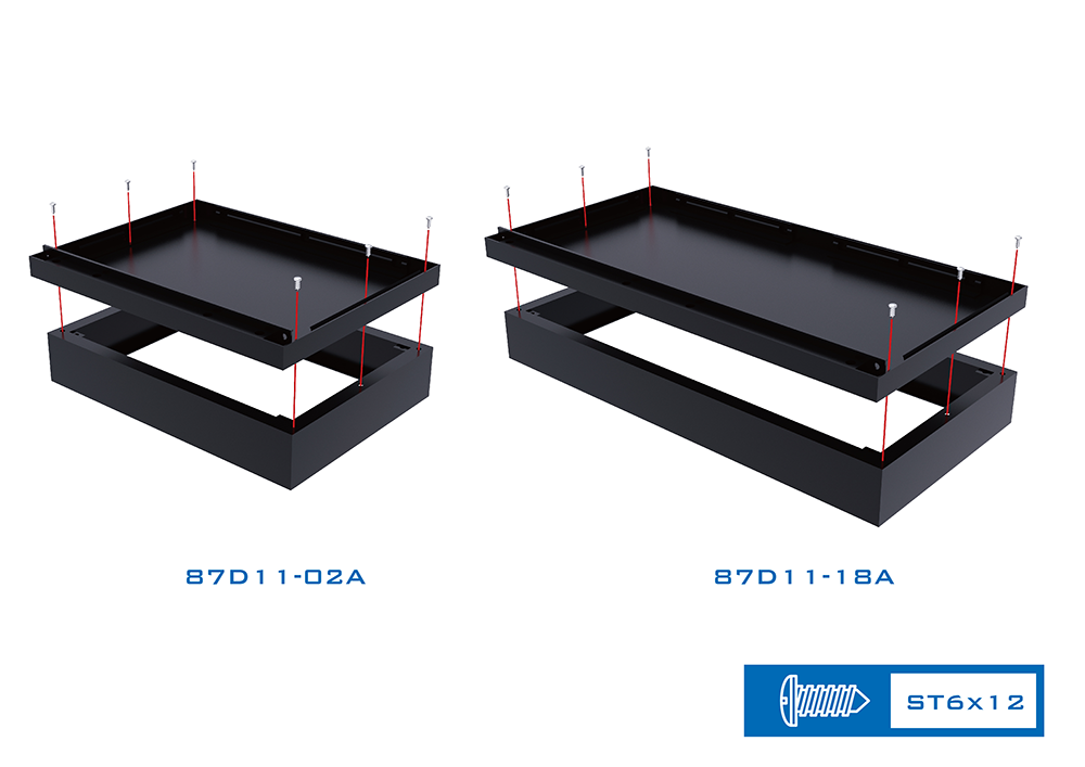
Cover up the base set with the bottom plate, then tighten the screws from above.
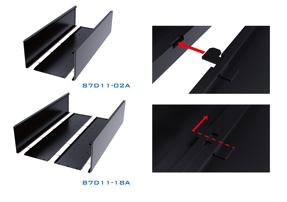
Connect three sides of the main body of the cabinet. Align the latches with the corresponding gaps and pin the components upward in order to form the body into a U shape.
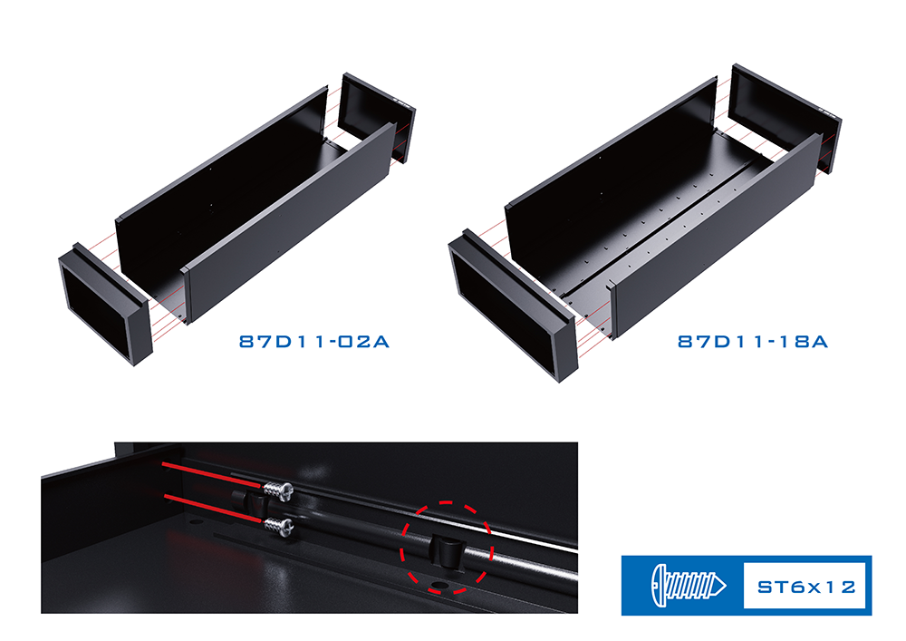
The following step is to connect the main body with the base set and the top plate. All latches need to be pinned correctly to make the cabinet firm and steady. Remember to tighten the screws forward from the base set. (Two screws are respectively needed on the both sides of the upper part and lower part.)
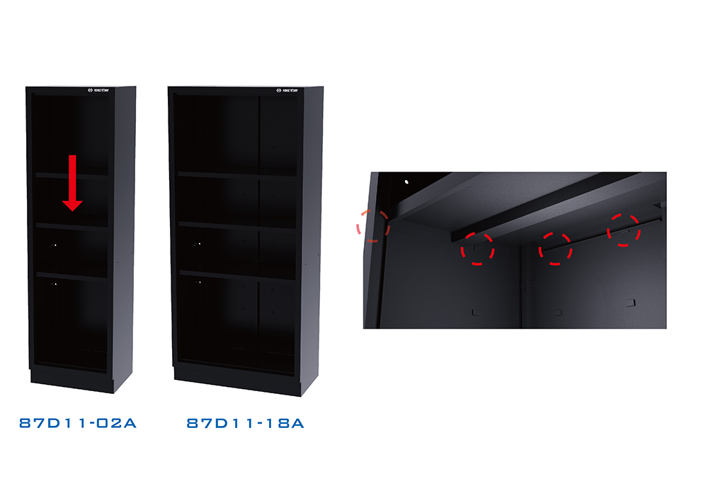
It’s time to place the partitions into the cabinet. Please note that latches are designed on the front, right, left and the back side. It is important that the latches on the back side need to be plugged into the gaps of the partitions and not just simply lying the partitions on top of the latches.
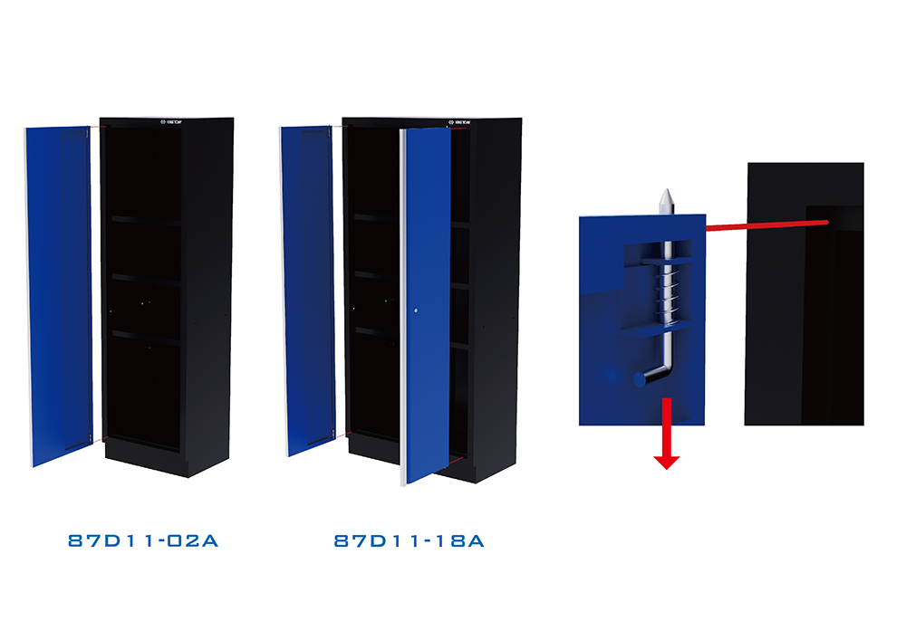
Installing the doors will be the final process of assembling a tall cabinet. Pull the handle, which is inside the door and near the rotate end, downward. Let go the handle after aligning the corresponding gap, and the door will be successfully installed.
Units Connections
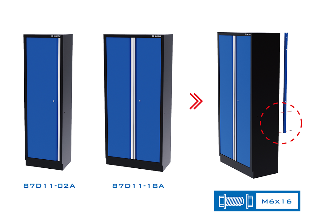
Now the tall cabinet on the side is completed. Attach and screw the pillar on the back of the tall cabinet. (If this tall cabinet will be arranged on the left side of the system cabinet, the pillar should be screw on the right side of the back of the tall cabinet. On the contrary, screw the pillar on the left side of the back to arrange the tall cabinet on the right side.)
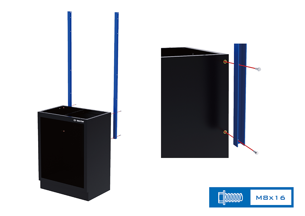
Follow up with setting up the bottom cabinet and the pillars of each unit. The initial step is to screw two pillars (production code 87D11-071A) on the back of the bottom cabinet (production code 87D11-03A, 87D11-04A, 87D11-05A, 87D11-25A, 87D11-11A). Directly screw on with bolts and the locking positions that are designed on the bottom cabinet.
| Opened Door Cabinet | 87D11-03A-KB 87D11-03A-KG |
| 4 Drawers Cabinet | 87D11-04A-KB 87D11-04A-KG |
| 5 Drawers Cabinet | 87D11-05A-KB 87D11-05A-KG |
| 7 Drawers Cabinet | 87D11-25A-KB 87D11-25A-KG |
| Trash Bin With Paper Holder | 87D11-11A-KB 87D11-11A-KG |
| Pillar | 87D11-071A-B 87D11-071A-G |
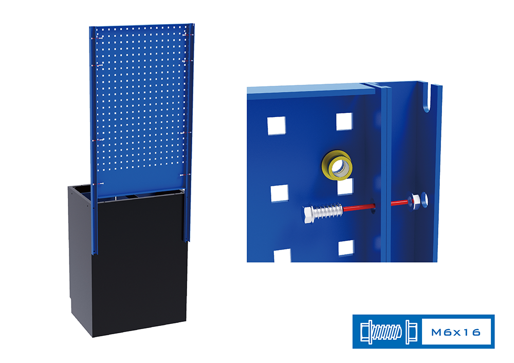
The next step is to install the back panel (production code 87D11-06A) between two pillars. Use the bolts and the nuts to dock and screw on the back panel with the pillars on the right and left side.
| Back Panel | 87D11-06A-B 87D11-06A-G |
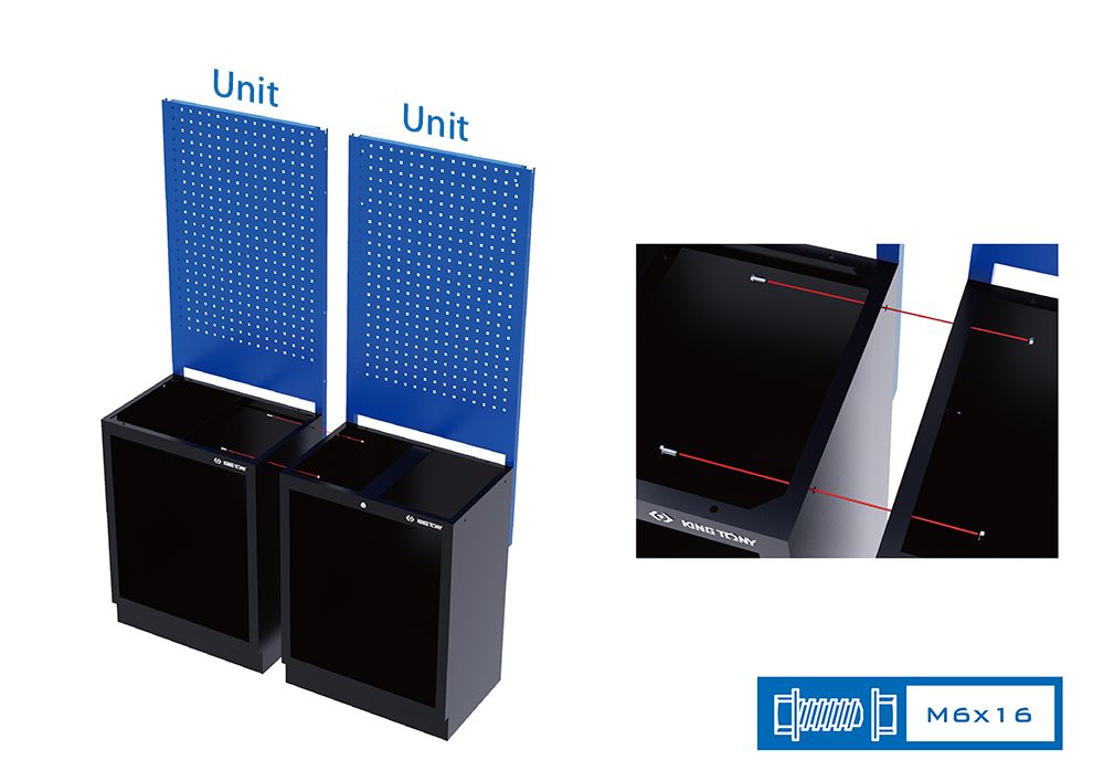
Every unit should be attached and screw on to each other in the following process (A unit involved a set of a bottom cabinet, a back panel that connects with two pillars, and a wall cabinet. Nevertheless, a tall cabinet is categorized as one unit. The unit in the following example hasn’t apply a wall cabinet yet.). Use the bolts and nuts to screw on the locking positions that are on the top of the right and left side of the bottom cabinet.
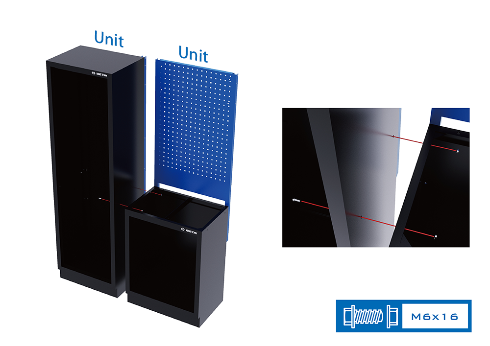
The graph above indicates the method of screwing the tall cabinet on the side and the unit beside together.
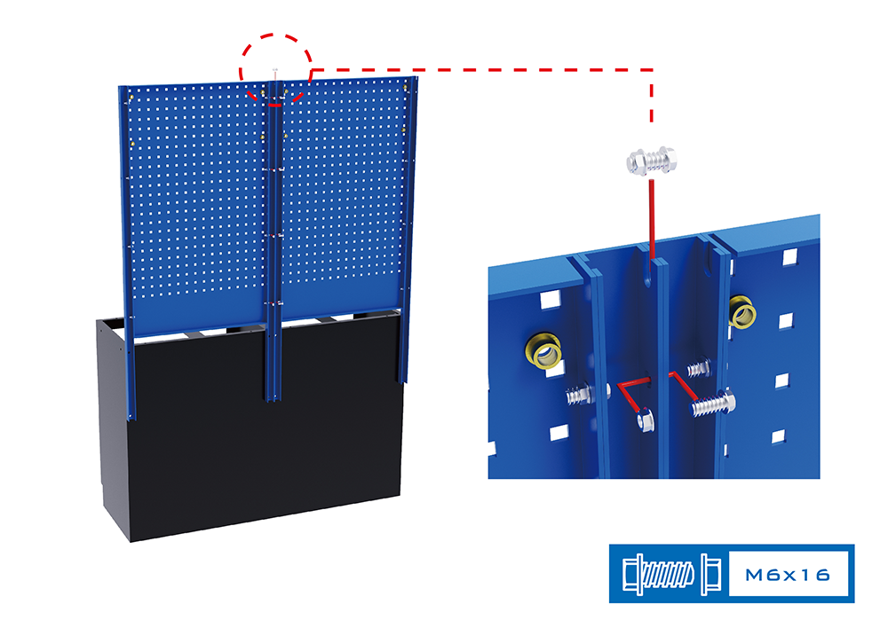
After finishing the attachment of the bottom cabinets, screwing the back panels will be the next step. Screw the pillars that are beside each other together. The gap on top of the pillars can be used as positioning beforehand, then tighten the screws of the rest of the locking positions.
Boards
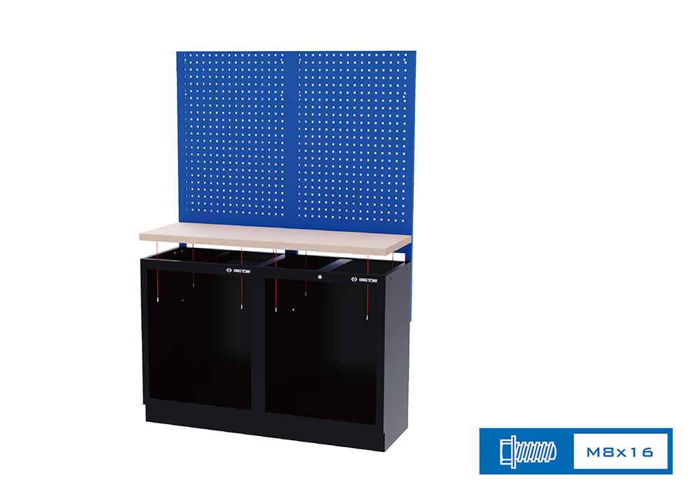
It’s time for the process of installing a board (Wooden boards’ production code 87D11-xxA or stainless boards’ production code 87D11-xxSA). The graph demonstrates the method of screwing a board for two units. Placing the board on the lower cabinets, then screw the bolts upward from the interior of the bottom cabinets.
| Pressed Wooden Board 87D11-xxA |
87D11-08A | 1360*465*38mm |
| 87D11-09A | 2042*465*38mm | |
| 87D11-10A | 681*463*38mm | |
| Stainless Board 87D11-xxSA |
87D11-08SA | 1360*465*38mm |
| 87D11-09SA | 2042*465*38mm | |
| 87D11-10SA | 681*463*38mm |
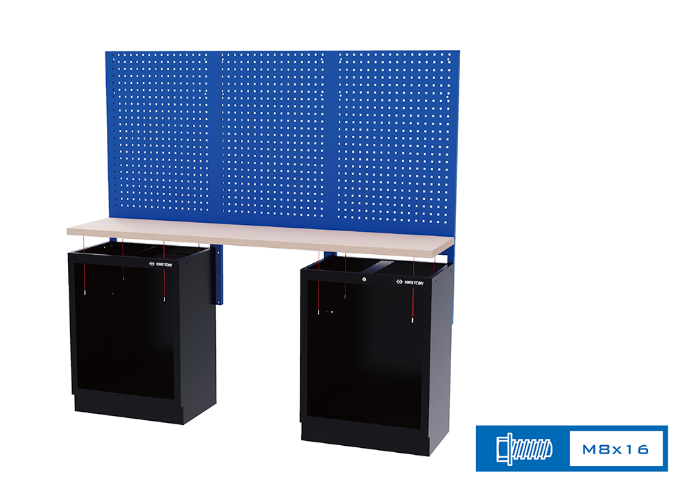
The graph above depicts the method of screwing a board for three units. It is noticeably that the three units normally come with a tool trolley in the middle, which implies that the back panel in the center should be attached with the other two beside it beforehand. Screw the bolts upward from the interior of two bottom cabinets in order to steady the board.
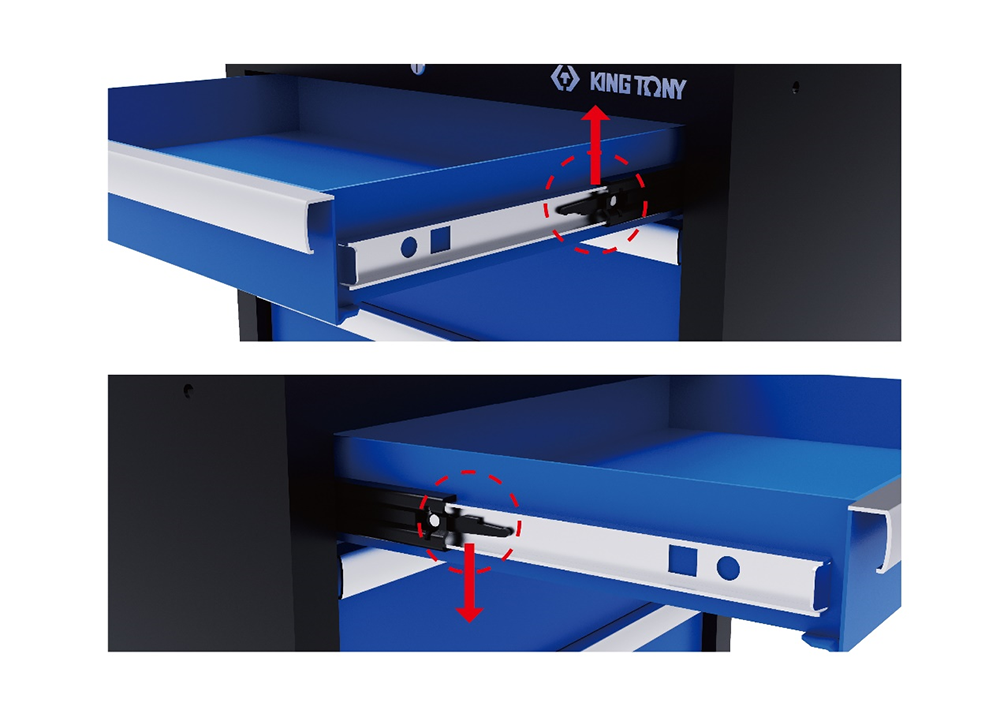
If your bottom cabinet is consisted of drawers (production code 87D11-04A, 87D11-05A, 87D11-25A), the drawers need to be dismantled in advance. As the graph demonstrates, a black mechanical structure can be seen on the right and left sliding rail after the drawer is opened. Please note that the right side of the drawer should be lifted up and the left side should be pressed down when it comes to taking out the drawers, and the working space for the installment of the board will be made after.
| 4 Drawers Cabinet | 87D11-04A-KB 87D11-04A-KG |
| 5 Drawers Cabinet | 87D11-05A-KB 87D11-05A-KG |
| 7 Drawers Cabinet | 87D11-25A-KB 87D11-25A-KG |
Corner Cabinets
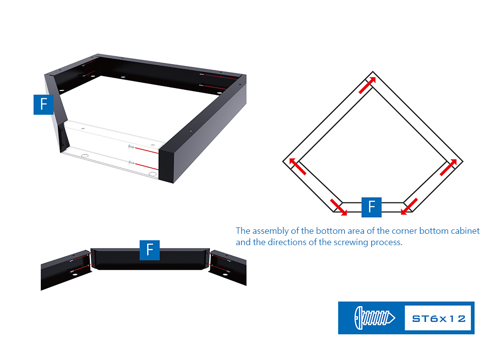
If your arrangement of the system cabinet includes corner cabinets, you should start the process below by assembling the bottom area of the corner bottom cabinet (production code 87D11-13A). According to the instructions of the graph and assemble the five components into a pentagon shape’s base set.
| Corner Bottom Cabinet | 87D11-13A-KB 87D11-13A-KG |
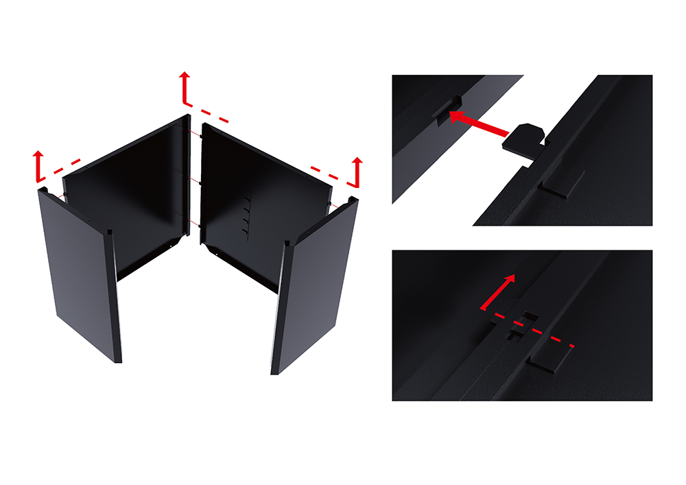
Put aside the finished base set and build up the four sides of the main body of the corner bottom cabinet.
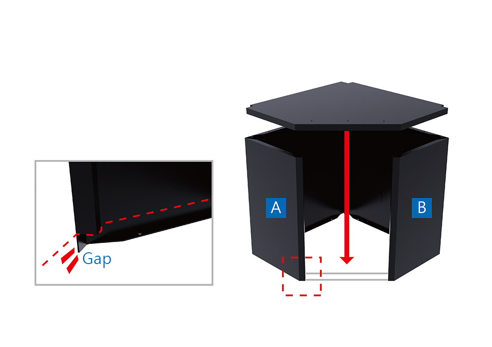
After assembling the four components of the main body, install the pentagon bottom plate under the corner bottom cabinet. It is noticeably that, according to the graph, there are gaps at the bottom area on the bending part of the A and B component that can fit in the thickness of the bottom plate. The placement of the bottom plate and the bending parts below can remain the steadiness and firmness of all five components.
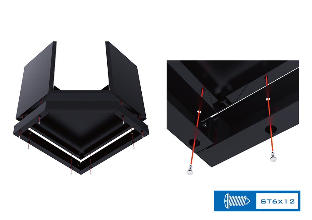
Dock the base set and the main body with the corresponding pentagon shape. Screw upward through the hollow beneath the base set in order to screw the main body and the bottom plate together.
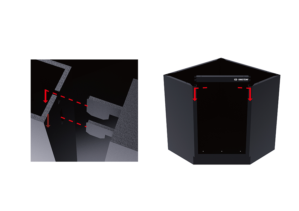
Follow up with the installment of the cross beam that is with a KING TONY logo.
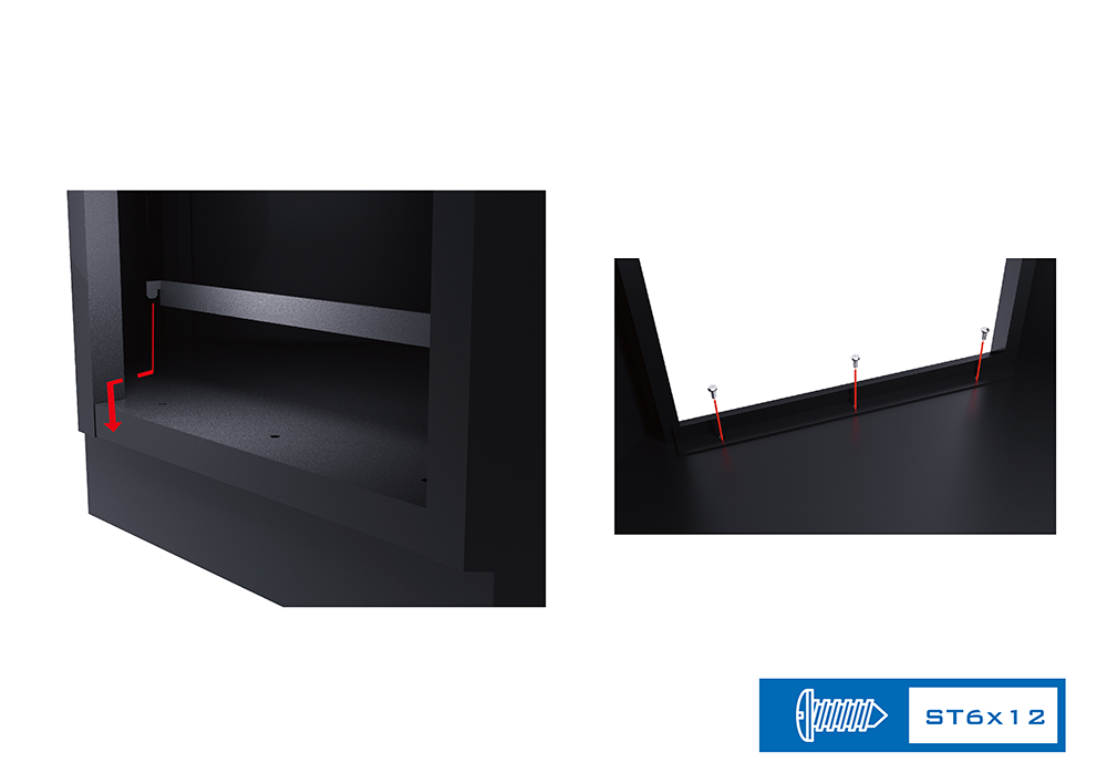
The next step is to apply the door arrester. Tighten the screws from above in the interior in order to firm the corner bottom cabinet.
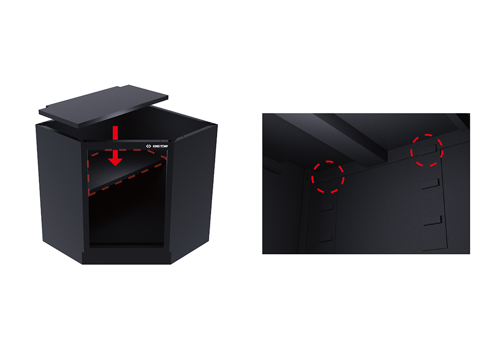
Place the partition of the corner bottom cabinet from above. Please note that the latches should be correctly aligned.
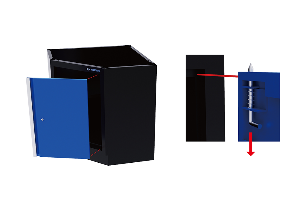
Install the door, and the corner bottom cabinet is completed.
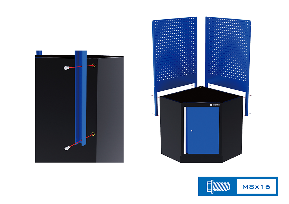
Set up the pillars (production code 87D11-071A) and the back panels (production code 87D11-16A) on the sides of the corner bottom cabinet.
| Pillar | 87D11-071A-B 87D11-071A-G |
| Corner Back Panel | 87D11-16A-B 87D11-16A-G |
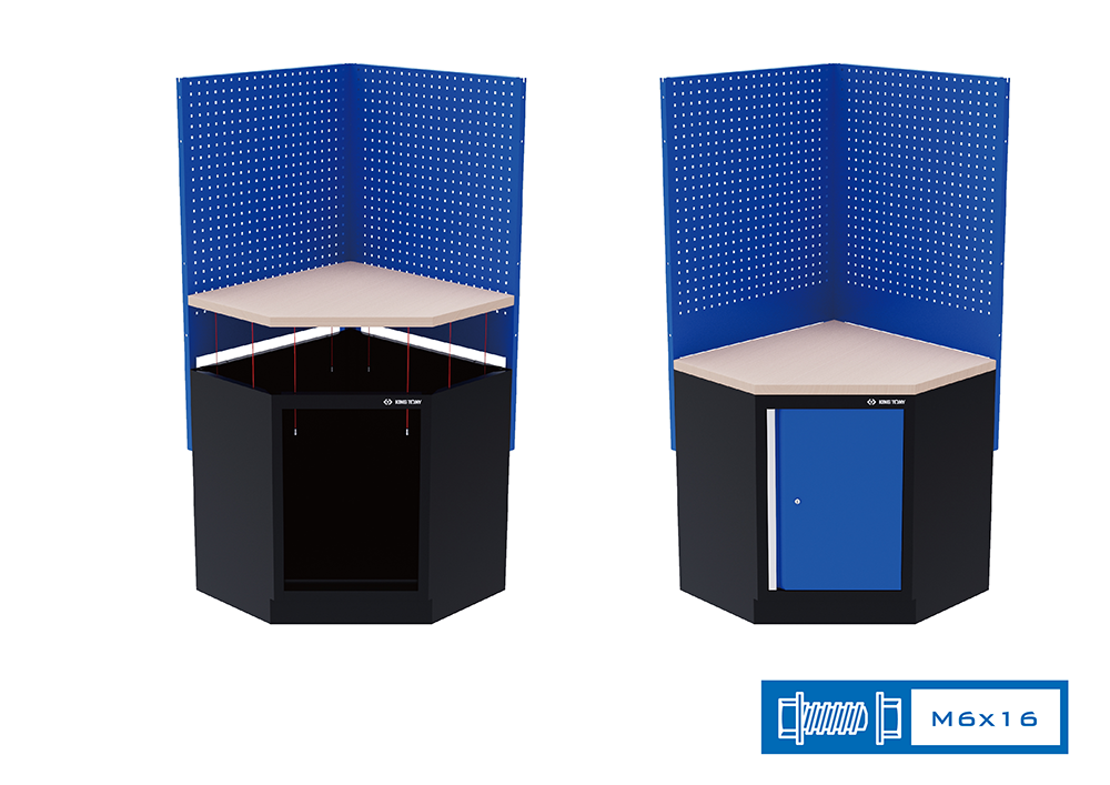
Screw on the board of the corner bottom cabinet (production code 87D11-14A or 87D11-14SA).
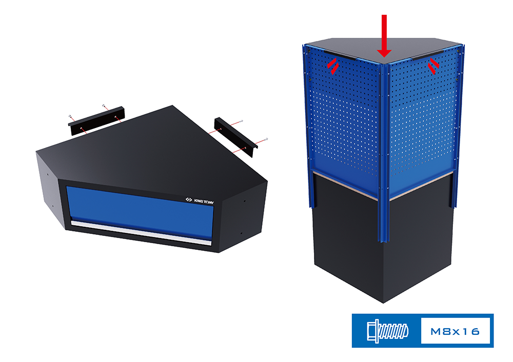
Screw on the left and right support hangers on the back of corner wall cabinet (production code 87D11-15A), then the corner wall cabinet can be hung on the back panels, as the graph depicts. Since now, the corner cabinet is done and can be connected with other completed system cabinets.
| Corner Wall Cabinet | 87D11-15A-KB 87D11-15A-KG |
Wall Cabinets
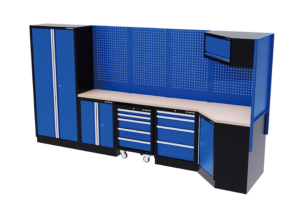
Now all units of the system cabinet, including tall cabinet and corner cabinet, are attached firmly. Therefore, it’s time for assembling the wall cabinets.
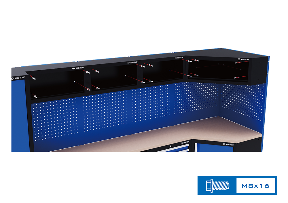
The assembly of the wall cabinets (production code 87D11-01A, 87D11-17A, 87D11-15A, 87D11-21A, 87D11-22A) can set up the bolts and washers on the hole sites on the back panel in advance, then hang the wall cabinets and tighten the screws.
| Wall Cabinet | 87D11-01A-KB 87D11-01A-KG |
| Rolling Shutter | 87D11-17A-KB 87D11-17A-KG |
| Corner Wall Cabinet | 87D11-15A-KB 87D11-15A-KG |
| Extra Wide Wall Cabinet | 87D11-21A-KB 87D11-21A-KG |
| Double Door Wall Cabinet | 87D11-22A-KB 87D11-22A-KG |
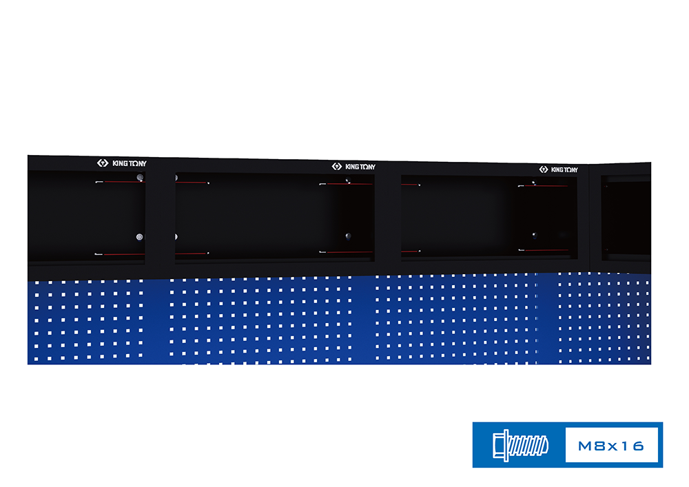
Last but not least, remember to tighten the bolts and nuts of the wall cabinets next to each other.
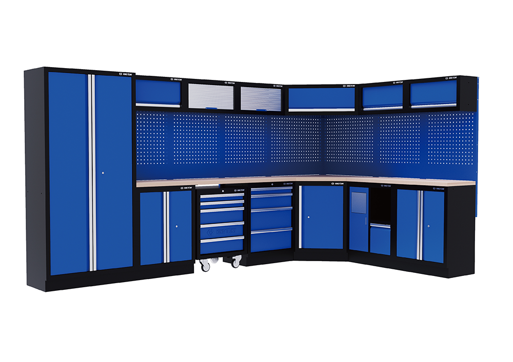
The assembly of the system cabinets is completed. Isn’t is really easy just by following the steps of the process?
Still, the rearrangement of the system cabinet, such as adjustments or applying new units, can be implemented in the future.All you need to do, is to pay attention to the corresponding hole sites to modify the whole set, and feel free to design a system cabinet of your own!
Recommended Products
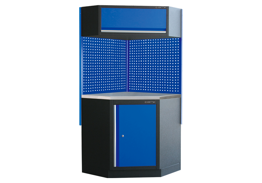
Corner Bottom Cabinet (Stainless Steel Board, black & blue)
87D11X06SA-KB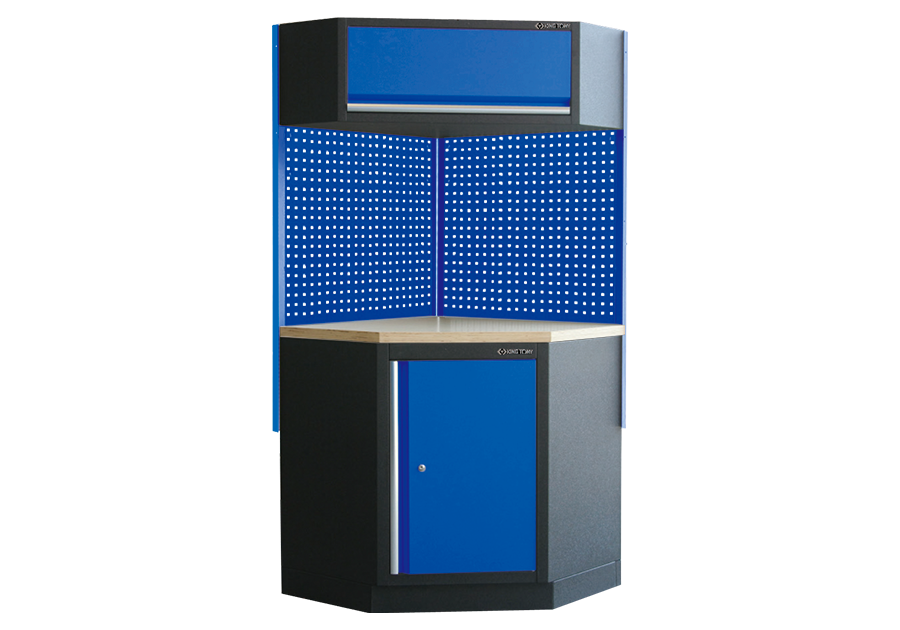
Corner Bottom Cabinet (Pressed Wooden Board, black & blue)
87D11X06A-KB
Pillar (blue)
87D11-071A-B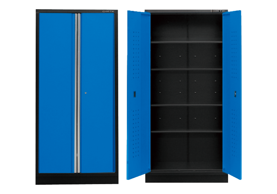
Tall Cabinet (black & blue)
87D11-18A-KB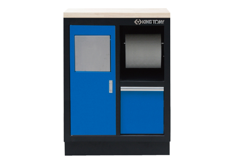
Trash Bin With Paper Holder (black & blue)
87D11-11A-KB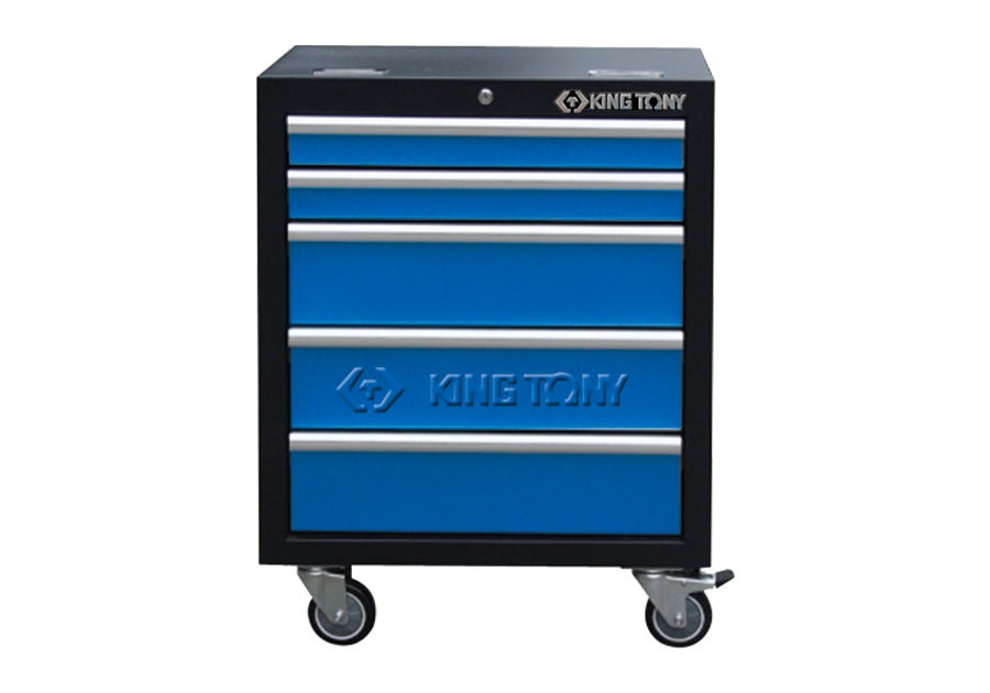
5 Drawers Cabinet (black & blue)
87D11-12A-KB
Back Panel (blue)
87D11-06A-B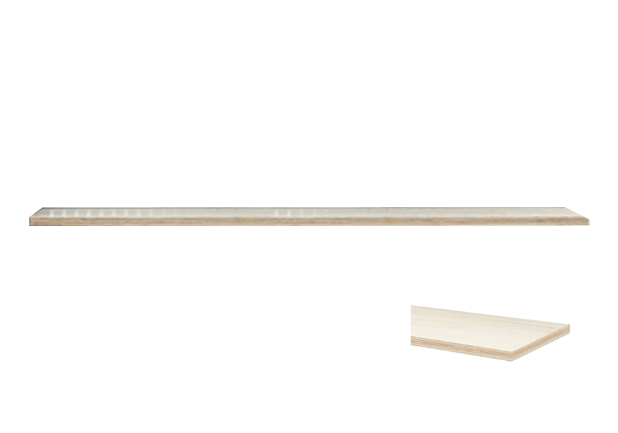
Pressed Wooden Board
87D11-xxA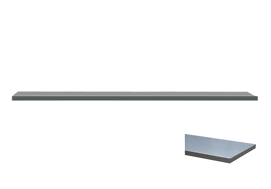
Stainless Board
87D11-xxSA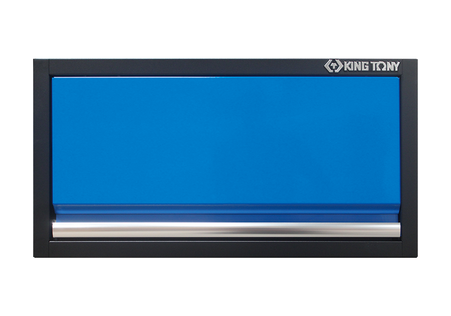
Wall Cabinet (black & blue)
87D11-01A-KB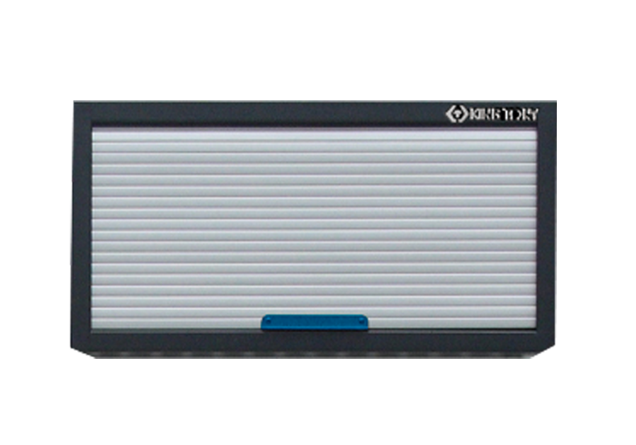
Rolling Shutter (black & blue)
87D11-17A-KB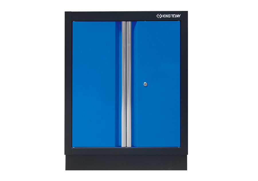
Opened Door Cabinet (black & blue)
87D11-03A-KB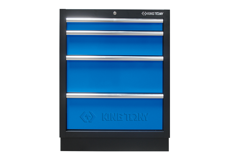
4 Drawers Cabinet (black & blue)
87D11-04A-KB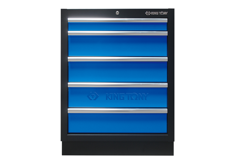
5 Drawers Cabinet (black & blue)
87D11-05A-KB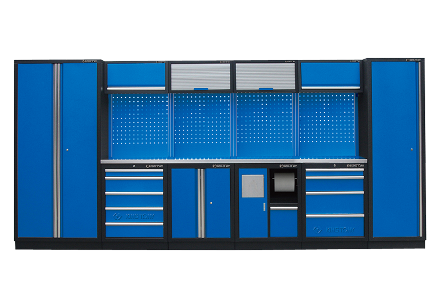
Object-Oriented Organization (black & blue)
87D11X02SA-KB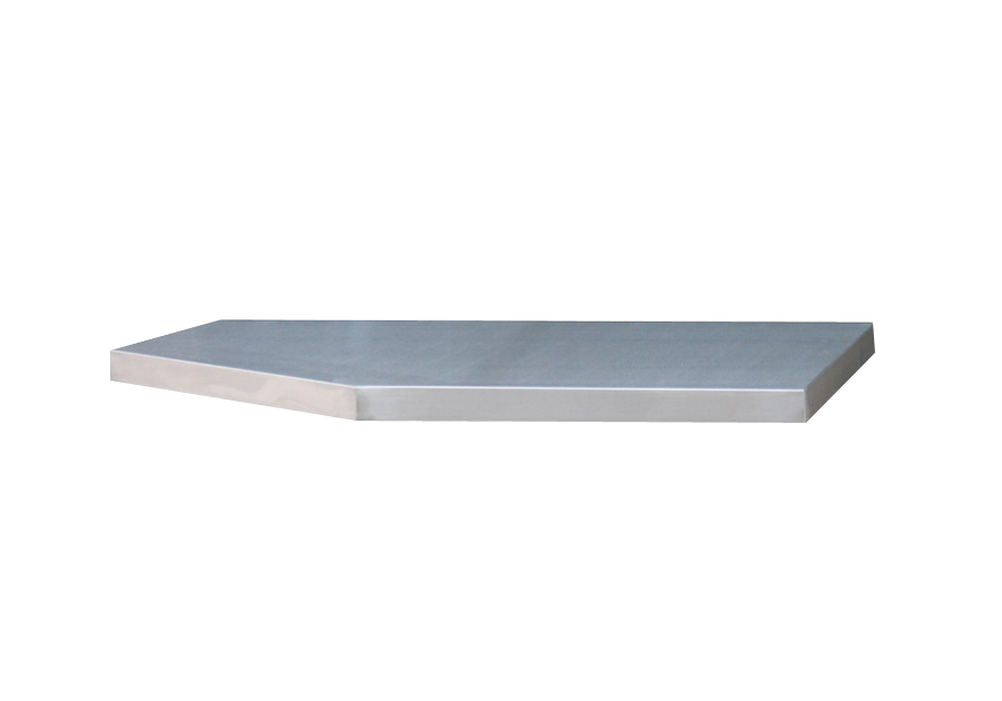
Stainless Steel Board
87D11-14SA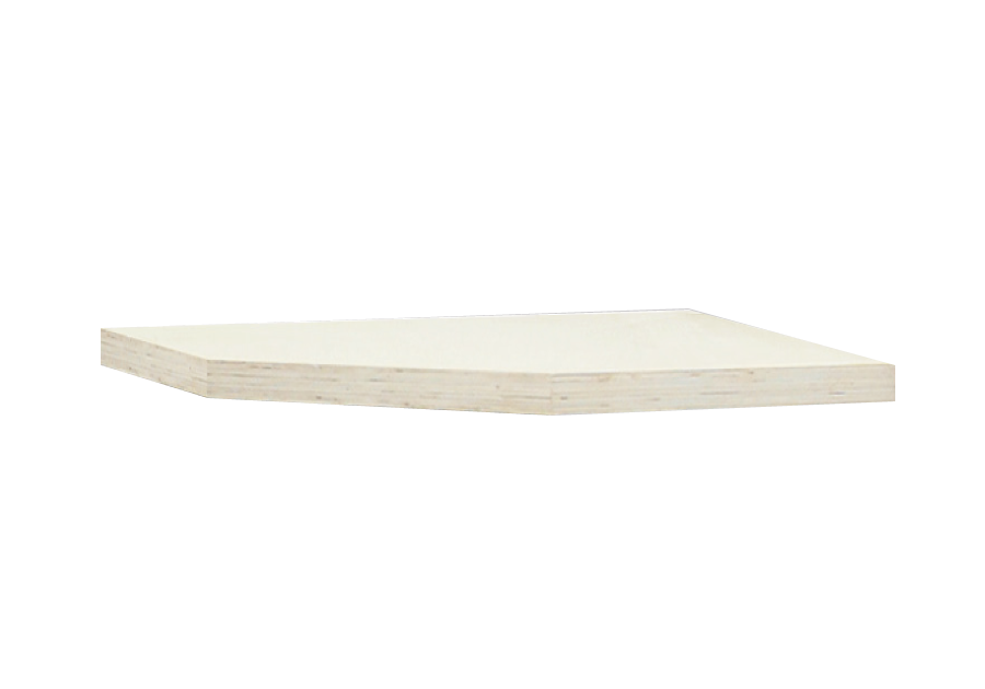
Pressed Wooden Board
87D11-14A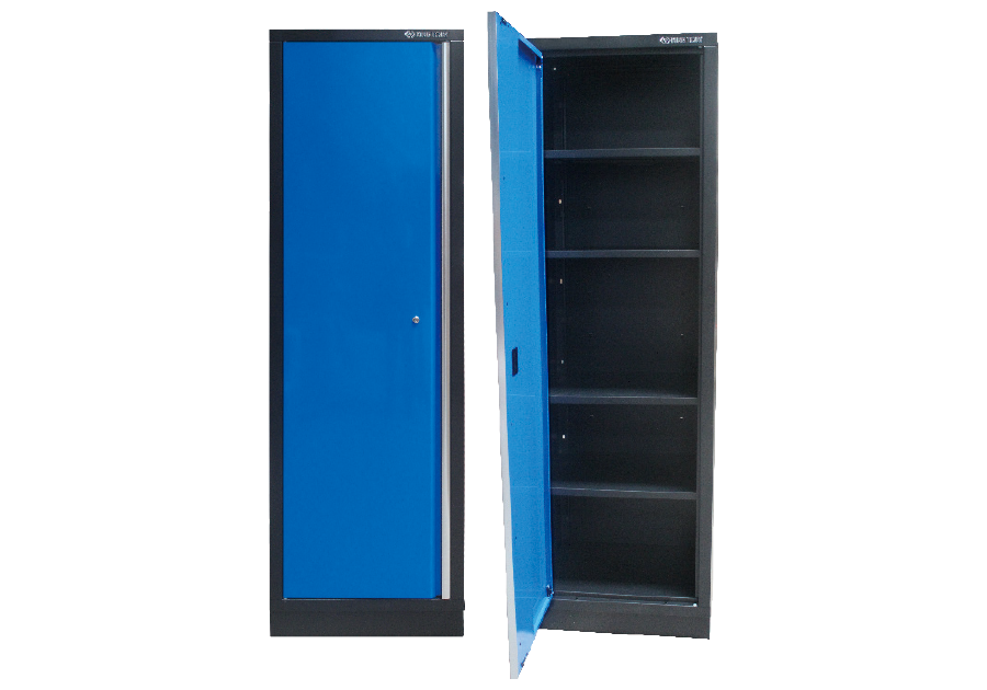
Tall Cabinet (black & blue)
87D11-02A-KB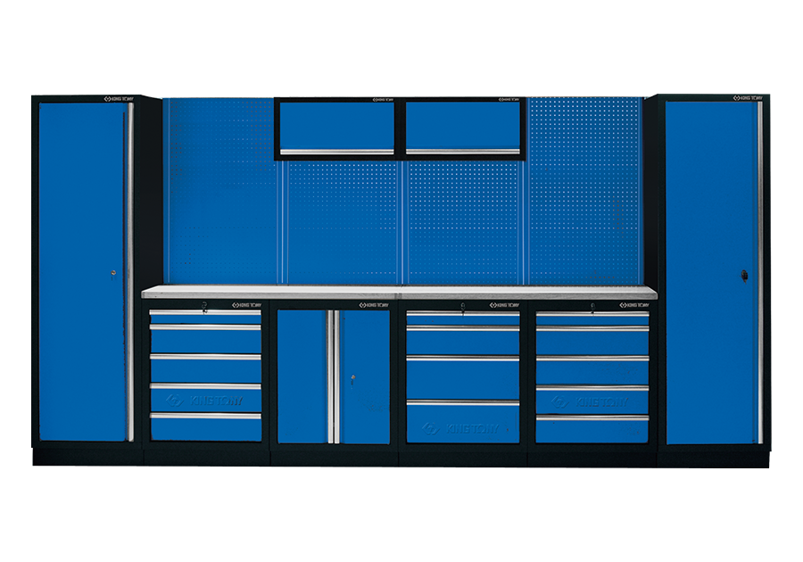
Object-Oriented Organization (black & blue)
87D11A-KB
Corner Wall Cabinet (black & blue)
87D11-15A-KB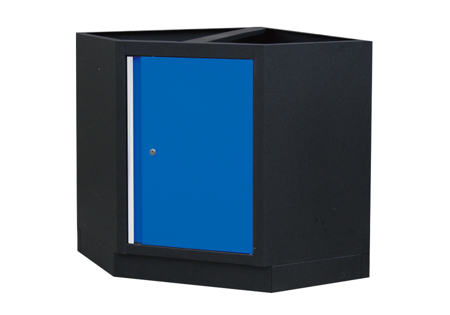
Corner Bottom Cabinet (black & blue)
87D11-13A-KB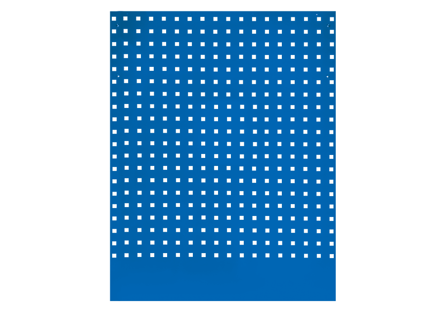
Corner Back Panel (blue)
87D11-16A-B